Sunday, December 30, 2007

Software Correlator - II

The angular resolution of radio telescopes can be improved by using the principles of interferometry. Interferometry depends upon detecting the combination of voltage signals assumed to be originating from the same source. In a simple two-element radio interferometer, the signals from a point source alternately arrive in phase and out of phase as the Earth rotates and causes a change in the difference in path from the radio source to the two elements of the interferometer. This produces interference fringes in a manner similar to that in Young's double-slit interference experiment, shown below.


The figure below shows how two waves from the same point source reach the two antennas on ground with a certain geometric path difference. If we multiple the two voltages generated at the antennas due to the waves reaching their respective locations, an interference pattern is observed (see third figure further down). Note how the appearance is exactly identical to the interference pattern generated by a two-slit interferometer using two slits as point sources, shown above.


The 'geometric' path difference due to spatial orientation of the source is similar to the path difference in 2-slit interference experiment. We probe phenomenon of 'temporal coherence' in 2-slit Young's experiment, that is we study the stability of phase difference between two sources (slits) over time. If the phase difference betwee two slits varied randomly, fringes will not have any absolute dark fringe ('zero' of intensity).


On the other hand, in 2-antenna interference,
the phase difference arises due to different locations of the 2 antennas as seen by the source. If the source was not a point source on the sky, fringes will not be perfect (no absolute zero of intensity). Thus, we study 'spatial coherence' of waves, that is if our source has a finite size.

Saturday, December 29, 2007

Software Correlator - I

(Hopefully, the first of many entries on this subject)

Mandar is working to create a program which will replace a bulk of old, creaking machines at GMRT and other similar synthesis-imaging instruments, which produce a stream of cross-correlations between different antennas that are separated from each other by a huge distance.

The first (baby) steps are to create a program to compute cross-correlations from a stream of numbers. Then, we develop the same algorithm for an input of quantized numbers. After correcting for source delays (fringe-stopping and fractional delay correction), we compute an FFT of the cross-correlation series, to obtain the power spectrum of correlations. Finally, we tie this bit with astronomical source co-ordinates.


Sunday, December 23, 2007

Data Acquisition System


We would like to make radio maps using Earth-rotation aperture synthesis . This technique requires us to record raw voltages at two antennas and compute complex visibility (cross-correlation) for different frequency channels.

The block diagram of the receiver and acquisition is shown in the figure on the left.

Each of 4 antennas will have a heterodyne receiver system which will translate a signal at the radio frequency (RF) of 73.9-MHz to an intermediate frequency (IF) of 1.9 MHz.

Four such signals reach the data acquisition system marked in the diagram. Each signal will be converted to digital using a 12-bit ADC, and then sampled at the rate of 0.5 MHz using only the most significant 2-bits.

Aniket carried out feasibility studies and design of the DAS to acquire Nyquist-sampled voltages from a bandwidth-limited signal (0.25 MHz). These quantized voltages are stored on a computer disk. There is a provision of acquiring from 4 antennas, so total data rates are 0.5*4 = 2 M-samples/s. Each sample consists of 2 bits each. Hence it is 8 M-bits/s = 1 MB/s storage rate on a PC.

Thursday, November 29, 2007

Antenna Length, RF Band and Impedance Matching

Our antenna band appeared to be shifted to 71 or 76 MHz.

Preeti and Roopa were looking up reasons for which the antenna might not be working at the desired frequency. They came across this fact on this page.


Antenna length


The length of a dipole is the main determining factor for the operating frequency of the dipole antenna. Although the antenna may be an electrical half wavelength, or multiple of half wavelengths, it is not exactly the same length as the wavelength for a signal travelling in free space. There are a number of reasons for this and it means that an antenna will be slightly shorter than the length calculated for a wave travelling in free space.

Hence, we feel that we have actually used a longer length than necessary...giving us a smaller frequency at 72 MHz. We will try reducing the length tomorrow and checking.

Also regarding the impedance matching..a Sleeve Balun is commonly used in VHF range. You can find more details on this page .

Wednesday, October 17, 2007

Bandwidth and antenna windings

Our dipole antenna element was fixed on wooden frame using nails. The dipole wire was wound around a nail to make it taut. When we introduced a wound around the nail, they acted as an inductors on ends of the wire (Rad's comment with a chuckle).

We need to put plastic caps on each end, and then use some material to fix the dipole wire, possibly some rope or hard plastic cover on usual copper wire. see this link.


As for the interference outside the "allowed band" of the dipole, let us wait for Onkar to fetch the co-axial cable from NCRA/TIFR, Pune.

Monday, October 15, 2007

Antenna and the bandwidth


We put up our first dipole antenna element on Friday (?) afternoon. Here is Roopa trying to keep the antenna wire taut, and Onkar's pic does not need a caption ;-)

The picture on the right shows the band. Even though Onkar tried to measure the length of the dipole as LAMBDA/4 on each side, the band is centered on 71.5 MHz. What gives? The bandwidth is barely 1 MHz, kind of a let down. At the same time, there is a lot of interference from the surroundings. Perhaps our antenna wire (not a co-axial yet) is too prone to pickup from around.

Tuesday, August 28, 2007

AD633 for multiplier


Vamsi suggests using Analog Devices' AD633 as the multiplier in our project. The circuit consists of a standard implementation mentioned in the datasheet. (Fig. 3).


Specifications
Transfer Function
[(X1–X2)(Y1–Y2)/10] + Z
Slew Rate (V/µs
20V/µs
Supply Voltage (V max)
±18V
Supply Current (max)
6mA
Temp Range
-40 to 85°C
Package
DIP/SOIC

From Analog Devices website. The datasheet.

AD633 seems cheap, and very popular. Good for it. Also, AD seem very forthcoming to give free samples. I will try something about that.

The development board for PIC18F2455

The previous post contains the link to the datasheet of the PIC18F2455. That thing is huge, some 428 pages. Instead, here is the link to the development board of the same controller. With the development board, I hope, it will be easier to handle USB protocols. (Without it, it seems simply impossible). I havn't been able to fix myself on either of the modules till now. The options are:
1)the dlpdesign module that mandar discussed
2)this PIC module
3)Since I am comfortable with the 8051 architecture, I would like to use a 8051 based controller, am trying to find a suitable one. Any help will be appreciated :-)

Here is the link:
http://www.sparkfun.com/commerce/product_info.php?products_id=762

Monday, August 27, 2007

Using a USB PIC

The USB microcontroller I have in mind is the PIC 18F2455.

Here is the link for the datasheet. ww1.microchip.com/downloads/en/DeviceDoc/39632b.pdf

This microcontroller not only offers upto 8MHz internal clock, but also has features like setting a self sampling rate through software, an inbuilt ADC (not sure if we can use it though). It provides for having 2 different rates for running the controller and for USB data transfer!

Monday, August 20, 2007

Dipole Antenna

Hi guys,
I have got 1kg (~50m) of aluminium wire (gauge 12) for making the dipole antenna. I got a good deal for Rs. 230/-. Copper wire is pretty expensive and 16m will cost Rs. 800/-. We can buy the copper wire whenever needed. We would be making a wooden stand in the workshop soon.

Friday, August 17, 2007

Virtual COM ports, and Noise Generation


Contacted my instructor at IGCAR today regarding use of the DLP245M module.He says the data rate of 8 Mbps should hold for our signal, but suggested that the transfer from the module to the computer might not be that fast.Therefore, we might have to investigate use of a larger buffer for storing the 8-bit data after acquisition.

A good thing for possible coding in C language is the VCP (Virtual COM port) feature in the DLP 245BM. This makes the module look like another COM port to the PC, but without the speed restrictions.According to the datasheet,

"Commands to set the baud rate are ignored – the device always transfers data at its fastest rate regardless of the
application’s baud rate setting. The latest versions of the drivers are available for download from DLP Design’s website at http://www.dlpdesign.com."

According to what I have heard recently from Amit, reading data from a COM port in C is possible. So, this could give us our basic acquisition system. <Still a bit confused about the data rate mentioned in the datasheet..8 million bits per second....i.e.1 MBps.. Does it mean that data can be sampled at that rate or that data is only transferred to the computer at that rate?..>

Still at a low regarding generation of random data for noise centered around a particular frequency in C. Forums on DSP pretty silent about noise generation around a particular frequency. I might try doing it in MATLAB next week.


Powered by ScribeFire.

Tuesday, August 7, 2007

Comedi for errors !

Software lib for possible use. hat tip Mandar...


Comedi - The Linux Control and Measurement Interface
Index
Introduction
Download
Documentation
Mailing list
Supported
hardware

Manufacturers
Applications
Bug Tracking


Links
Linux
Debian
RTAI
David Schleef

Introduction

The Comedi project develops open-source drivers, tools, and libraries for data acquisition.

Comedi is a collection of drivers for a variety of common data acquisition plug-in boards. The drivers are implemented as a core Linux kernel module providing common functionality and individual low-level driver modules.

Comedilib is a user-space library that provides a developer-friendly interface to Comedi devices. Included in the Comedilib distribution is documentation, configuration and calibration utilities, and demonstration programs.

Kcomedilib is a Linux kernel module (distributed with Comedi) that provides the same interface as Comedilib in kernel space, suitable for real-time tasks. It is effectively a "kernel library"

Monday, August 6, 2007

USB port card

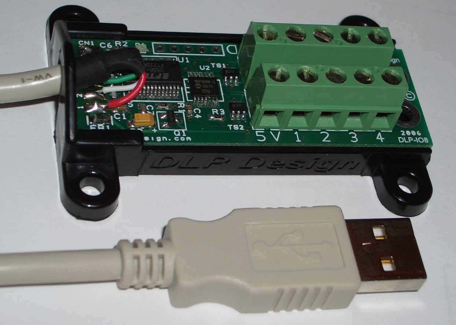
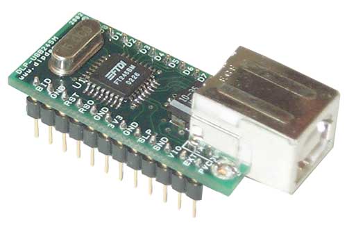
Mandar has a very good idea of using a USB port based acquisition. Below are details of DLP-IO8-G 8-Channel Data Acquisition Board and DLP-USB245M USB Adapter, from this link and that link. Other similar option from DLP is DLP-TXRX-G USB Adapter.


DLP-IO8-G 8-Channel Data Acquisition Board


DOWNLOADS
Test Application V1.0
VCP Drivers
FTDI Driver Installation Ap Note for Win98
FTDI Driver Installation Ap Note for Win 2000

  • 8 Channels: Digital I/O, Analog In, Temperature (requires DS18B20 sensor, purchased separately)
  • Easy to use single byte commands
  • USB 1.1, 2.0 Compatible
  • Rev 2 silicon from FTDI
  • No in-depth knowledge of USB required
  • Call or email DLP Design for volume pricing


DLP-USB245M USB Adapter


DOWNLOADS
Test Application V1.0
DLL Drivers
DLL Driver Programmer's Guide
VCP Drivers
FTDI Driver Installation Ap Note for Win98
FTDI Driver Installation Ap Note for Win 2000

  • Add USB connectivity to your next project
  • Up to 8 megabit per second data rate
  • USB 1.1 Compliant
  • Simple FIFO interface to MCU/FPGA/CPU/etc...
  • Rev 2 silicon from FTDI
  • No in-depth knowledge of USB required
  • Call or email DLP Design for volume pricing

Block diagram (till I can scan the paper copy)

The data acquisition of a band-limited signal has the following broad steps:


  1. DC removal


  2. 2-bit ADC (0.5 MHz speed)


  3. Collect 4 such samples at one time (for simplicity, copy the same signals 4 times)


  4. Build a sampler, of 0.5 MHz.


  5. One could take 10 MHz signal, and use every 20th pulse (simple counter) for sampling.


  6. Put together four 2-bit samples on a bus with an isolator for i/o.


  7. Feed the signal to the data acquisition card sitting in the PCI slot of a PC.

BITS Telescope

BITS Goa Radio Telescope : Software Correlator

Thanks to Aniket and Mandar, we will get a data acquisition card interfaced to a PC by next semester.

All the card does is to accept AC voltages of 250 KHz bandwidth, digitize it (2-bit ADC) and sample it at Nyquist rate (500 KHz). Four samples (2x4 bits = 1 byte) are then packed together on the fly to form one byte. The resultant one-byte is stored on a PC for processing. So, the pipeline looks as below


--- signal ---- >>-- ADC -->>--Linux PC-->>- FILE
(0.5 V AC________3-level____bit packing
0.25 MHz band)___2-bit_________program


ADC has two comparators (NE 521 ?). Depending upon the input, one of the the following 00 (-2), 01 (-1), 10 (+1), 11 (+2) is the output of the ADC.

The sampler signal of 0.5 MHz samples the ADC output voltages. Four of the samples are fed to the acquisition card through data cables.

The data rates are slow, 500 k Bytes per second. Given the modern computer disk rates, it is possible to sustain a on-the-fly bit packing program in PC. The program accepts 4 bytes, and based on a precalculated table, stores corresponding 1-byte output onto a file.